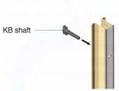
Insert the KB shaft into theshaft hole in the KB joint unit.(7 shafts for an L=1800 unit)
Please handle with care as the KB shaft is frangible.
2.
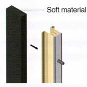
Insert the soft material.
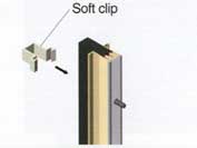
3.
Fix the soft material with thesoft clips.(4 clips for an L=1800 unit)
■ Installation [TYPE-A,TYPE-B common]
1.
Mark the mounting position on the formwork and drill holes.
2.
Fix the inducing plate.
Misalignment of K-B Joint and the inducing plate may degrade the ability to aggregate cracks. Please make sure that they are installed in the same straight line.
1.
Set KB Holder on the marked position.
2.
Set the inducing plate.
3.
Set the other inducing plates.
Please arrange the parts so that the plate is set straight between the holders.
3.
Fix the unit to the formwork.
1.
Set up the panel board.
2.
Insert the KB shaft into the hole from the structure side.